Building Your Own ROS Robot: Chassis, Wiring, and Safety Insights
Written on
Chapter 1: Introduction to ROS Robotics
Creating a successful ROS robot requires careful planning and execution. I recently discovered the Weddell 2 ROS Robot, designed by the user pokpong on Thingiverse, which closely matched my vision for a robust robotic system. My goal was to construct a robot sizable enough to accommodate a Raspberry Pi, various sensors, a reliable battery pack, and a microcontroller. Faced with sourcing the original motors, I decided to remix the design for more affordable gear motors equipped with encoders. You can find the modified files available for download.
The chassis is fabricated from PETG using an Ender 3 Pro printer. To ensure a successful print without warping, the components require rafts and supports, which must be carefully trimmed away with a hobby knife. Due to the slicer's behavior, holes often print smaller than intended, so I recommend drilling them to the correct size.
Section 1.1: Chassis Design and Modifications
The original design utilized German gear motors that proved difficult to obtain and were quite pricey. Instead, I opted to redesign the baseplate to accommodate more affordable gear motors with integrated encoders. My aim was to create a robot that prioritizes torque over speed. To achieve the desired speed range, I used a robot wheel speed calculator to determine the necessary RPM.
I modified the base STLs using OpenSCAD, filling unnecessary holes and adding new ones for motor mounts. The same plate is printed twice to create mirrored sides. The assembly of the sides and decks is done using M3 socket head screws and locknuts.
Subsection 1.1.1: Safety Considerations
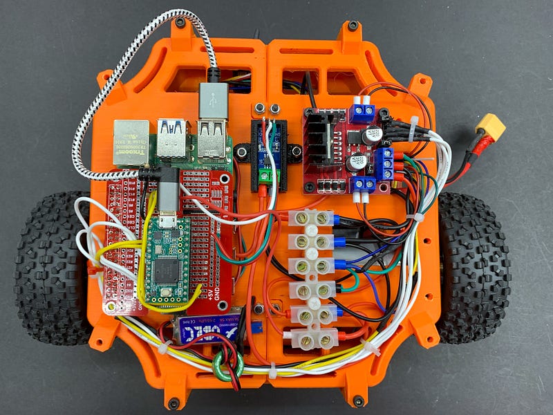
When constructing a larger robot, particularly one with autonomous capabilities, safety must be a priority. With significant stored energy in the batteries, the risk of unexpected robot movement poses a threat to people. Here are some safety measures I implemented:
A suitable fuse is crucial to protect against short circuits or unexpected overcurrent. I calculated the stall current of both motors, the maximum current draw of the Raspberry Pi, and the current usage of the LIDAR, then multiplied the total by 1.25 to select the nearest standard fuse value. Additionally, the robot can monitor the current at the fuse — the software can disable the motors if current levels approach unsafe limits.
To prevent shorts, all connections in the terminal block are insulated or covered with heat shrink tubing. The power wires are appropriately sized for their current, and connections to terminal blocks are crimped with ferrules to avoid exposed strands. The power switch is easily accessible, and I plan to add an emergency stop button for added safety. To mitigate the risk of a runaway robot, I limited the top speed to just a few meters per second, ensuring people can move out of the way if necessary. This design also allows for a smooth drive with ample torque.
Currently, I'm using a 3S 2200 mAh lithium polymer battery made for RC vehicles. While this choice isn't ideal due to the lack of protection circuits, I am implementing measures to shield it from physical damage using both the robot frame and a custom-printed battery case. A proper charger compatible with my battery's chemistry is essential, and I treat LiPo batteries with the utmost care.
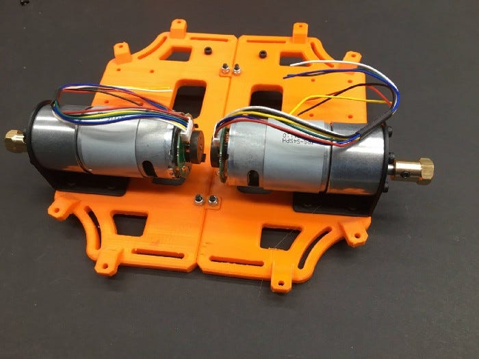
Section 1.2: Building the Motor Deck
For the build, I reused a 1" caster from a previous robot chassis, similar to roller ball transfer bearings. To achieve the necessary ground clearance, I chose a set of 85 mm wheels with tires. The included brass wheel adapter fits standard R/C car hex wheels, providing versatility for wheel selection.
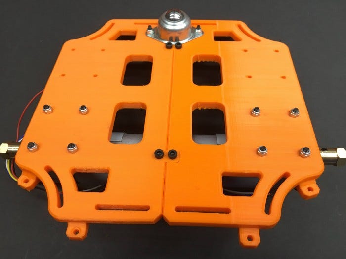
The design by pokpong incorporates clever pockets that securely hold M3 nuts — once the support material is removed, they lock into place. These vertical structures, referred to as "masks," come in various designs for sonar, battery sockets, and a Raspberry Pi camera. I opted for the camera mask and a plain mask for the remaining supports, which greatly enhance the robot's structural integrity.
To improve printability, I modified the masks to eliminate sharp edges that could reduce contact with the print bed, which previously caused failures during printing.
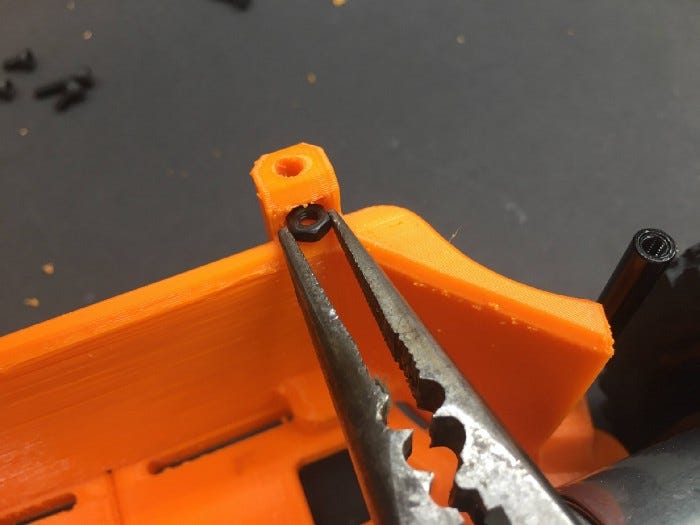
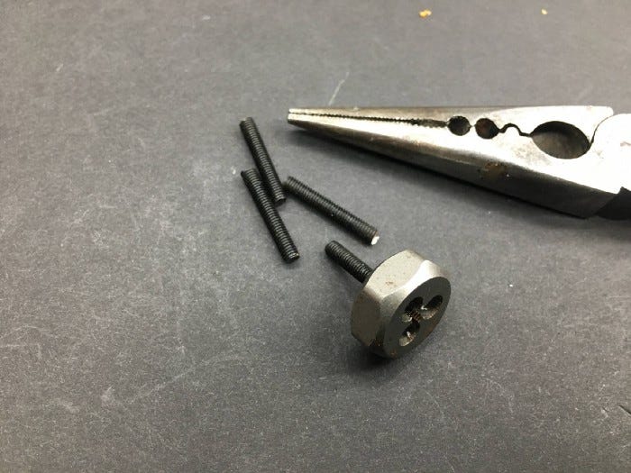
For vertical risers, I selected 50 mm black aluminum standoffs. The battery pack is positioned behind the motors. To connect the standoffs, I used M3 threaded rod. Lacking this component, I repurposed my longest M3 screws by cutting the heads off and cleaning the cut ends with an M3 tap.
Chapter 2: Deck Layout and Electronics
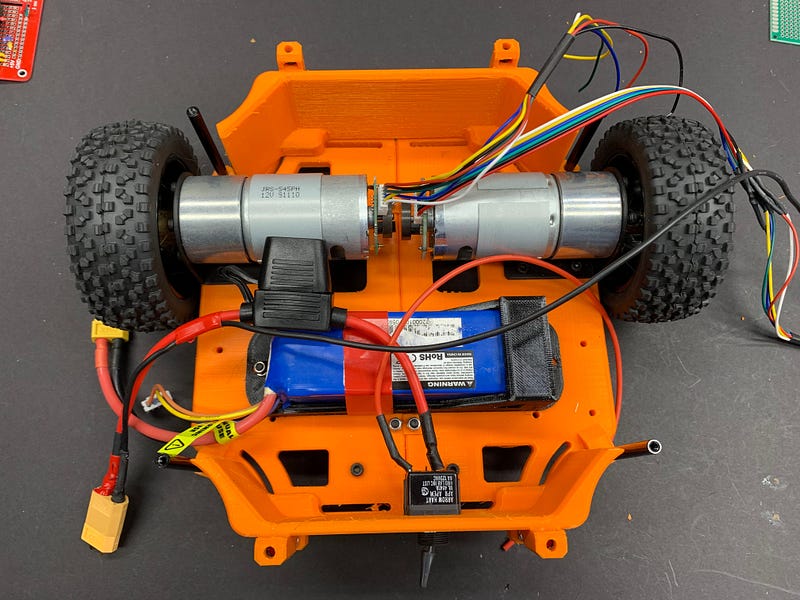
The deck layout is thoughtfully designed to facilitate wiring and allow for future expansion. Maintaining a low center of gravity is essential; therefore, I placed the battery on the bottom deck, along with the fuse and power switch.
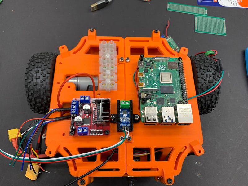
The second deck houses the electronics and power distribution. In the image below, you can see the mounted Raspberry Pi 4, along with a current sensor (blue) and motor H-bridge driver board (red). The white bar is a set of screw terminals for organized wire connections.
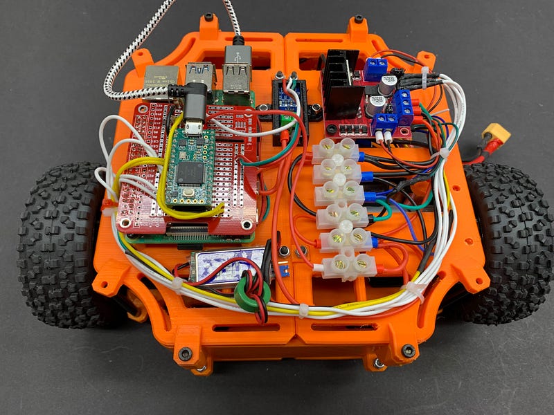
The Teensy microcontroller stacks on top of the Raspberry Pi on a small carrier board. I did not use the Pi expansion board, as power and communication are managed via USB. A 5V, 3A battery eliminator circuit, typically used in R/C aircraft, provides power to the Pi and Teensy. Power is directly soldered to the Pi's test pads, and PCB standoffs are 3D printed.
Wiring
I opted for silicone insulated stranded hookup wire for all connections due to its flexibility and ease of use. The power connections utilize heavier gauge wire to handle increased current. For voltage and ground connections, I implemented screw terminal blocks secured to the chassis with standoffs. Using a ferrule crimping tool with screw terminals ensures clean and reliable connections. In future builds, I plan to incorporate braided sleeves for additional wire protection.
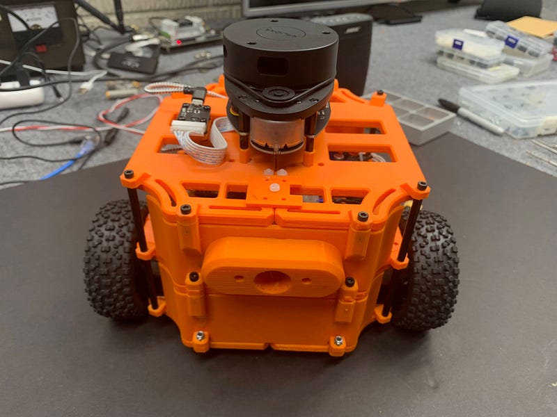
With the hardware assembly complete for now, I may consider adding another deck for an RGBD depth camera. I hope you found valuable insights for your own robot design and construction journey.
In the upcoming article, we will delve into the motor controller and base controller software that regulates motor speeds, tracks the robot's position, and publishes initial ROS topics!
Chapter 3: Learning ROS Through Video
In this first video, "Build a ROS Robot - Learn ROS with Me Part 1," you'll get a detailed guide on the initial steps in creating your own ROS robot.
The second video, "MakerSnack: Assembling and Testing Mini Round Robot Chassis with Raspberry Pi," showcases the assembly and testing processes for a mini robot chassis, providing valuable insights for your own builds.